Ikas Blender 3D ( 1 - Armature and Mesh )
![]() Introduction
- First animation - A
little more -
Constraints -
Weight -
Weight paint -Various
tricks
Introduction
- First animation - A
little more -
Constraints -
Weight -
Weight paint -Various
tricks
Armature
and Mesh:
Start by creating a chain of 3 Ika's roughly
resembling the figure below.

The first thing that needs to be done is to precisely name each branch. The purpose of this is critical because in the following operations, each branch will have to be attached by its name with either the entire or part of a given mesh. To do this, switch to edit mode ( TAB ), select the entire ika chain ( A ) and open the Edit Buttons window ( F9 ) to obtain this:

You
could keep the default names assigned in the column of buttons below
'Selected Bones', but for our example, it will be simpler to replace
these names with: B1, B2, and B3. ( To edit a name click on the right
side of the button, just after the text, then press Shift+Backspace
to delete the old text and enter the new name ). Also, press the
button 'Draw Names'. This is essential so that you will be able to
find the name within the framework of a complex work. Notice that
when the names are changed, the contents of the boxes 'child of' are
also changed. These boxes make it possible to define the
relationships between the branches. Click on the button indicating:
B2 and in the pop-up menu which appears, choose: B1 to see what
happens. The root of the third branch is now attached to the tip of
the first. Return things to their prior state and then ensure that
the IK button accross from B1 is pressed in. Experiment a little to
see the difference between when 'IK' is pressed in or not makes, if
you wish.
Create a cylinder and extrude it 5 times to obtain the result shown in the the figure below.

N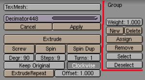 ow
it is necessary to determine the influence of the ika system on the
cylinder which will have to be divided into distinct sections for
which each one will be assigned to a branch of the armature. The
operation is very simple, especially if you already have experience
assigning multiple materials to a single object. The principle is
strictly identical and the work is done in the Edit Buttons window (
F9 ) using the column of buttons hi-lited in the image to the right.
(the cylinder must remain in edit mode so that it is visible ).
ow
it is necessary to determine the influence of the ika system on the
cylinder which will have to be divided into distinct sections for
which each one will be assigned to a branch of the armature. The
operation is very simple, especially if you already have experience
assigning multiple materials to a single object. The principle is
strictly identical and the work is done in the Edit Buttons window (
F9 ) using the column of buttons hi-lited in the image to the right.
(the cylinder must remain in edit mode so that it is visible ).
C lick
on the 'New' button and a new box will be displayed on which is
written 'Group'. Replace this text with B1 and repeat this action by
successively entering B2 and B3, which are the names of the three
branches of the armature. Be especially careful not to make a mistake
entering the names and always respect ( lower / upper ) case,
otherwise it will not work properly. Once the three groups are named,
click on the small white dash ('-') button on the left side of the
name, in order to select one of the three groups. The 'Delete' key
allows you to remove any group which is no longer required .
lick
on the 'New' button and a new box will be displayed on which is
written 'Group'. Replace this text with B1 and repeat this action by
successively entering B2 and B3, which are the names of the three
branches of the armature. Be especially careful not to make a mistake
entering the names and always respect ( lower / upper ) case,
otherwise it will not work properly. Once the three groups are named,
click on the small white dash ('-') button on the left side of the
name, in order to select one of the three groups. The 'Delete' key
allows you to remove any group which is no longer required .

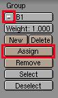 Select
the B1 group, then select some of the vertices of the cylinder ( B +
left mouse click and select ) as shown above and click on the
'Assign' button. The selected vertices now form part of the B1 group
and will be affected by the movements of the B1 branch of the
armature. Press the 'Deselect' button to de-select the group created
last, then select the vertices of the central part of the cylinder,
choose the B2 group in the list, assign, de-select and finish by
assigning the B3 group to the last two sections. By using the group
selected from the pop-up menu list and the 'Select / Deselect'
buttons, verify that for each group, you have correctly activated two
sections of the cylinder. If that is not the case, the 'Remove'
button allows you to remove the vertices that you have chosen for the
currently active deformation group. Note: For this type of
work, the keyboard short-cut keys 'Hide selected vertices' (H), 'Hide
unselected vertices' (Shift_H), 'Reveal' (Alt_H) and 'Select Swap'
(Available from the 'Specials' menu - W,7) are often very useful.
Select
the B1 group, then select some of the vertices of the cylinder ( B +
left mouse click and select ) as shown above and click on the
'Assign' button. The selected vertices now form part of the B1 group
and will be affected by the movements of the B1 branch of the
armature. Press the 'Deselect' button to de-select the group created
last, then select the vertices of the central part of the cylinder,
choose the B2 group in the list, assign, de-select and finish by
assigning the B3 group to the last two sections. By using the group
selected from the pop-up menu list and the 'Select / Deselect'
buttons, verify that for each group, you have correctly activated two
sections of the cylinder. If that is not the case, the 'Remove'
button allows you to remove the vertices that you have chosen for the
currently active deformation group. Note: For this type of
work, the keyboard short-cut keys 'Hide selected vertices' (H), 'Hide
unselected vertices' (Shift_H), 'Reveal' (Alt_H) and 'Select Swap'
(Available from the 'Specials' menu - W,7) are often very useful.
A
final detail before moving on to the animation itself: Parent the
cylinder to the armature. Right click the cylinder, Shift + right
click the armature, CTRL+P, then choose the option 'Use Armature'
from the pop-up menu which is displayed and then we're all ready.

Note: It is not always necessary to assign all of the vertices in a mesh to an armature. On the contrary, to leave a small section of vertices not assigned near the joints will often avoid unpleasent creases. You can sometimes leave 'intermediate bones' not managing any vertices at all to soften certain effects. An unassigned 'bone' is invisible when it is rendered, therefore it is often a good technique to use some invisible 'bones' as control points for the management of movements.