Ikas Blender 3D ( 4 - Constraints )
![]() Introduction
- Armature and Mesh - First
animation - A little more
- Weight
-
Weight paint -Various
Tricks
Introduction
- Armature and Mesh - First
animation - A little more
- Weight
-
Weight paint -Various
Tricks
Constraints:
Combined with the armature system, constraints offer an almost
unlimited range of possibilities for animation. Moreover, constraints
can also be applied to all of the types of objects available in
Blender. There are 4 types of constraints:
'Track to', 'IK
Solver', 'Copy Rotation' and 'Copy Location'. 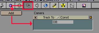 To
apply a constraint: Select an object and press the 'chain' icon
button in the menu header bar and then press Add to obtain this:
To
apply a constraint: Select an object and press the 'chain' icon
button in the menu header bar and then press Add to obtain this:
The
small white dash '-' button besides 'Track To' allows you to select
one of the four types of constraints. You can rename the constraint (
'Const' by default ) and the 'OB:' box in which you enter the name of
the object that you have selected, which you wish to have the
constraint exerted upon. Recall: The name must be entered exactly
with respect to upper/lower case letters, if it is not, the contents
of the dialog box will be erased. If the title bar changes to red -
attention! You have made an error and in matters concerning
constraints, when Blender is not content, Blender crashes! ( V2.20 ).
The .blend example files for this page, can be opened from the
various links located throughout the page.
1/
Track To: If you have
already used the CTRL +T ( Make track ) option, then you should not
find this feature too confusing. The selected object will have one of
its axes permanently oriented towards the indicated object. The most
typical example applies to the camera. To obtain the result shown
below, all you need to do is select the camera and enter the name of
the target object into the constraints dialog box.
Note: The target
object ( Empty ) does not have to be selected, it appears pink here,
only so that it is more visible in the image.
The
Animation buttons window ( F7 ) shown partially visible in the image
below with a portion of it hi-lited in red, does not really form part
of the new options, but it is probably a good idea to recall that the
object subjected to a constraint will perhaps not take the desired
orientation with your first try. Therefore, it will be necessary to
use this window to select the axis which must undergo the constraint.
In the case of tracking, the first 3 buttons in the group of 6
determine which axis is orientated towards the target, the following
3 buttons, in the same group, will orient the opposite axis towards
the target by performing an 180° rotation. The seperate group of
3 buttons ( 'Up' ) indicate which of the remaining two free axes will
be orientated upwards.
The
example is rather banal, but it best illustrates a means with which
to aim a camera. ( ex-01.blend )

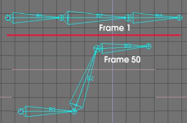
A
little more convincing example: Once again, use the armature
previously created and apply the two positions shown below to it, for
frames 1 and 50 ( as explained in the previous pages ) and then play
the animation. Next, add an 'Empty'. Select 'Bone' B3 in 'pose' mode
( Blue ) and create a 'Track to' constraint for the Empty before
playing the animation.
This
introduces some interesting possibilities. Each 'bone' can be
subjected to a particular constraint, each 'constrained' object
modifies the shape of the armature if it is moved. If, in this
example, it is a simple empty object which is used as a constraint,
it could also be a moving element. As if that was not enough to
create very complex movements, the same object can be subjected to
several different constraints produced by various objects.
Do
not forget to play a little with the x ,y ,z buttons in the Animation
buttons window to see the results. ( ex-02.blend
).

2/
IK Solver: This constraint generally relates to the origin (
the thickest part or root ) of a 'Bone'. Either in the same armature
or in another. When this constraint is defined, initially it is
necessary to provide the name of the armature which transmits it and
then the name of the source 'bone'. Once this is done, the source
'Bone' will attract the 'bone' subjected to the constraint towards
its root/base. The file ( ex-03.blend )
displays, at the top, a static armature ( which does not have any
animation key ). Its last element ( Bone.004 ) is subjected to an IK
Solver due to bone B3 of the second armature which is animated. When
you launch the animation, you will notice a "magnetized"
effect produced by the movement of the second armature.

In
the IK Solver dialog box, increasing the tolerance, increases a
little the radius anchoring (clearance distance) between the two
'bones'. Iterations determines the action (operating) radius and the
intensity of the magnetism. Increase this value if the "connection"
is not made fairly quickly or decrease it if the animation is
sluggish. ( Default Value = 500 ). A classic method consists in using
this form of constraint to add bones acting as 'handles' to manage
the global animation of an armature. It is this process which made it
possible to manage Ikas in the previous versions of Blender.
3/
Copy Rotation: Here, a small adjustment to the Edit buttons
window (F9) is essential ( With the armature selected ) click on the
'Draw Axes' button. With this done, pivot the empty so as to align
its axes as compared to that of the armature. The 'Animation buttons
window' (F7) will not be able to do anything here for you, if the
constrained object takes an unforeseen orientation. Once the
constraint has been carried out, the selected object will always
remain parallel to that which imposed the constraint. It is obvious
that if this last one is animated by a rotation it will be
transmitted to the constrained object during the animation.
3/ Copy
Location: This constraint allows you to lock the position of
the constrained object relative to the object named in the 'Target
Object' (OB:) constraints box. You can choose the axes on which the
object will be locked. The ex-04.blend
file contains a small animation using these types of constraints.